Call Us
+86-13486669457 中文简体
中文简体
 English
FL-24 SAE Split Flange Clamps 3000PSI
Cat:3000 PSI SAE Flange Clamps
1. Working pressure of SAE code 61 series flange clamps is 3000 PSI, 3,5 MPa (35 bar) to 35 MPa (350...
See Details
1. Working pressure of SAE code 61 series flange clamps is 3000 PSI, 3,5 MPa (35 bar) to 35 MPa (350...
See Details
1. Working pressure of SAE code 61 series flange clamps is 3000 PSI, 3,5 MPa (35 bar) to 35 MPa (350...
See Details
1. Working pressure of SAE code 62 series flange clamps is 42 MPa (420 bar). 2. SAE Flange clamps d...
See Details
1. Working pressure of SAE code 62 series flange clamps is 42 MPa (420 bar). 2. SAE Flange clamps d...
See Details
1. Working pressure of SAE code 61 series flange clamps is 3000 PSI, 3,5 MPa (35 bar) to 35 MPa (350...
See Details
1. Working pressure of SAE code 61 series flange clamps is 3000 PSI, 3,5 MPa (35 bar) to 35 MPa (35...
See Details
1. Working pressure of SAE code 62 series flange clamps is 42 MPa (420 bar). 2. SAE Flange clamps d...
See Details
1. Working pressure of SAE code 62 series flange clamps is 42 MPa (420 bar). 2. SAE Flange clamps d...
See Details
Introduction of hydraulic fluid power- flange connections with one-piece flange clamps and metric or...
See Details
The custom inclined flange is a specialized component used in various industrial applications to con...
See Details
The ring flange is a type of pipe flange that is designed to slide over the pipe and then be welded ...
See Details
The welding flange is a type of flange that is used in the welding process to join two pieces of met...
See Details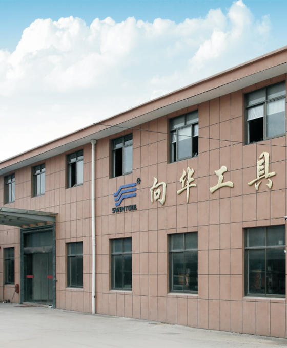
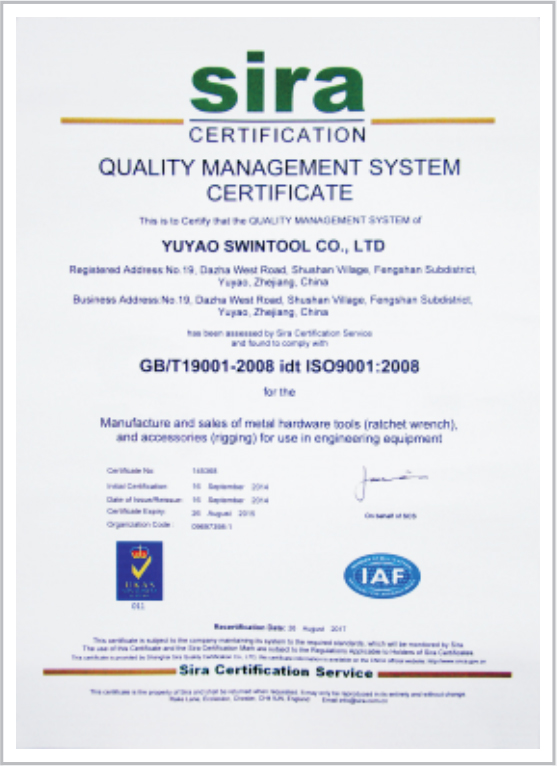
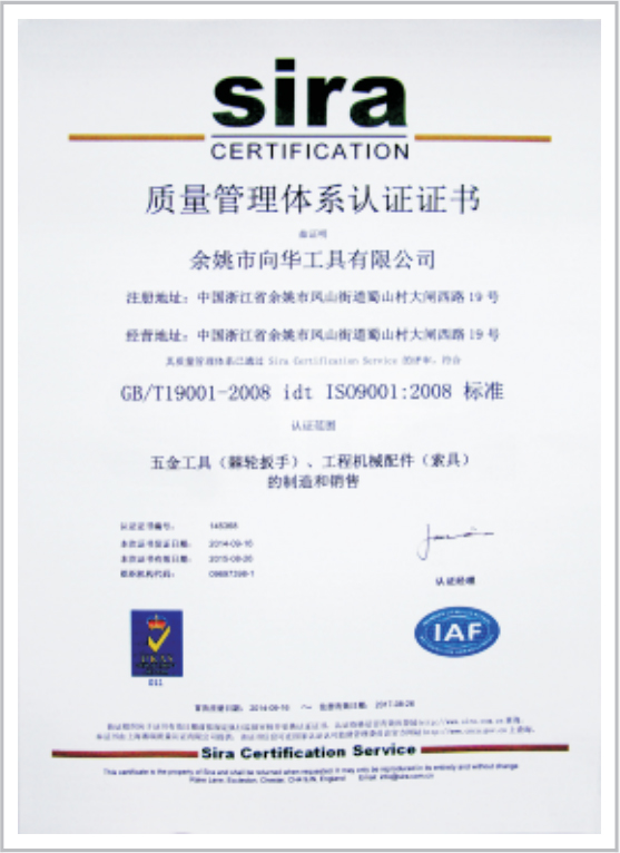
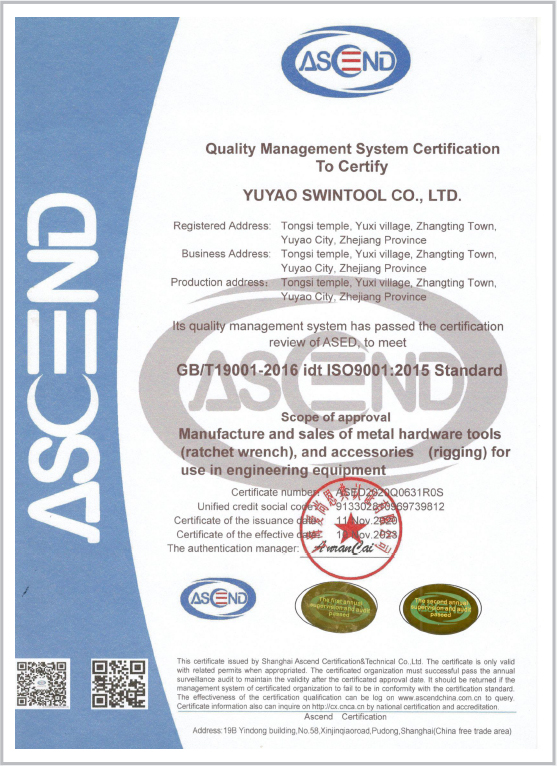
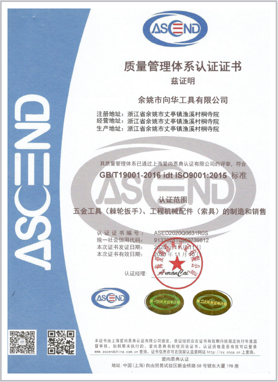
Swintool is professional China Stainless Steel SAE Split Flange Clamps Manufacturers and heavy duty SAE split flange halves factory, with a certificate of ISO 9001:2008.
Our range of products includes SAE flange clamps, turnbuckles, top link assemblies, ratchet turnbuckles, industrial ratchet wrenches. The advantages of our product are the following:
1. Flange Clamps: SAE J 518 (ISO 6162 -1/-2) standards, from hot forging, CNC machining in our factory. SWINTOOL also offers OEM solutions.
2. Turnbuckle: A manufacturer in turnbuckle DIN 1478 made of seamless steel pipe. 500-ton Horizontal hydraulic machine for pipe forming bigger diameter and longer length, also for drop forging.
3. Top link assembly: Professional processing technology of more than 15 years of experience, CNC precision machining, Hot forgings, heat treatment and strict assembling procedure.
4. Ratchet turnbuckle: As a top manufacturer and designer, we have our company standard of ratchet turnbuckles, also can design for your special need.
5. Ratchet wrench: We can design the Industrial ratchet wrench with heavy duty, big size and special purposes for original equipment manufacture. We offer custom OEM/ODM stainless steel heavy duty Code 61 62 SAE split flange halves

Copyright © 2023, Yuyao Swintool Co., Ltd. All rights reserved.
